I’m in the design process for a 2MHz 12V to 20V Boost Converter, and have landed on using EPC2218A FETs for now. I’ve downloaded the EPCGaNLibrary and “Example EPC2619.asc” LTSpice model to get started.
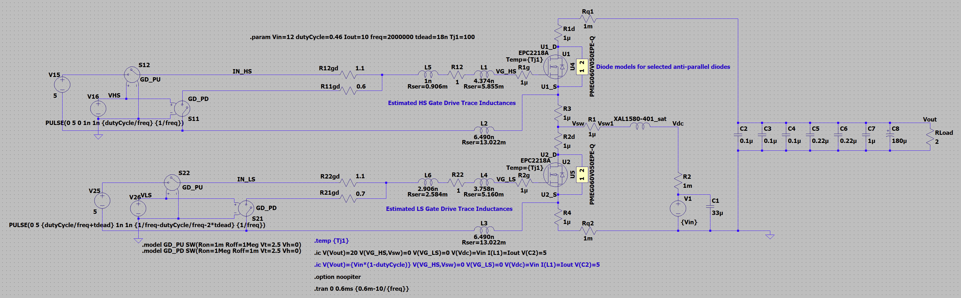
From there I’ve modified the example to be a boost converter and use models of the components I’ve selected (correct inductors, capacitors, etc.) I’ve then added in estimated trace inductance and resistances from my PCB Layout tool.
Here is the current model:
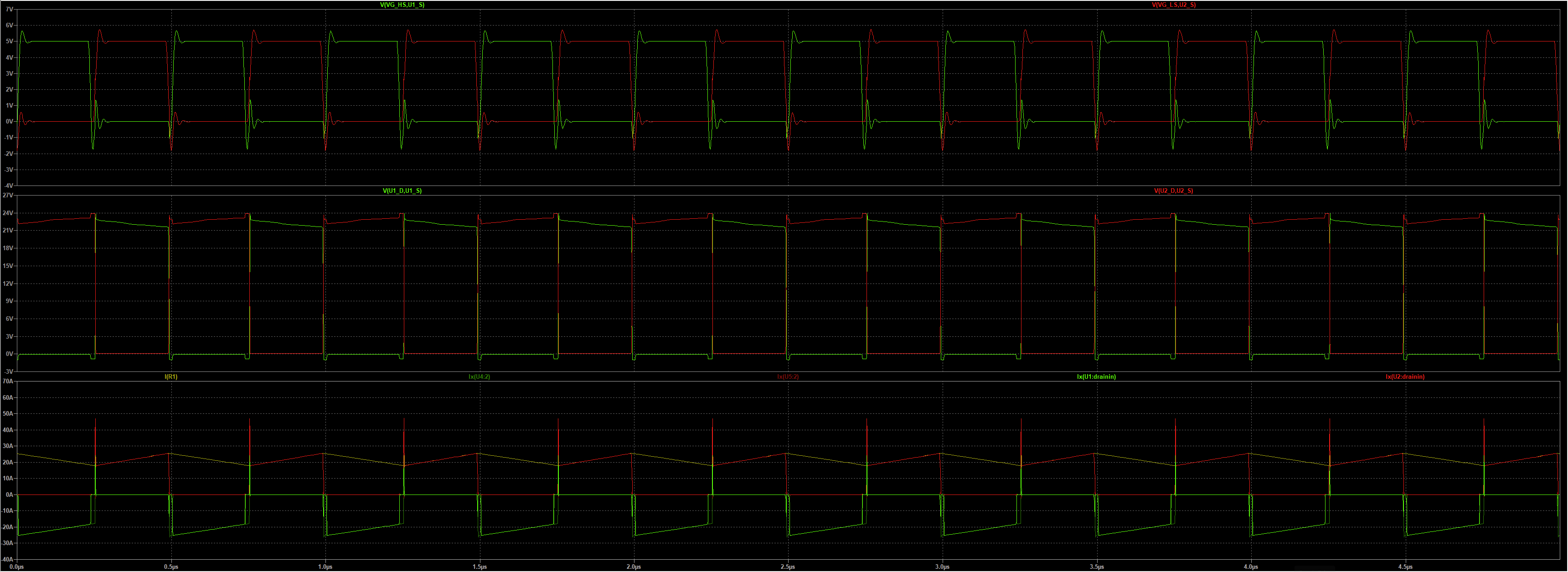
Now onto the “apparent” shoot-through issue. At first I thought it was some reverse recovery type issue (even though I know GaNFETs don’t have a reverse recovery time), so I added external diodes to confirm, and the issue is still present.
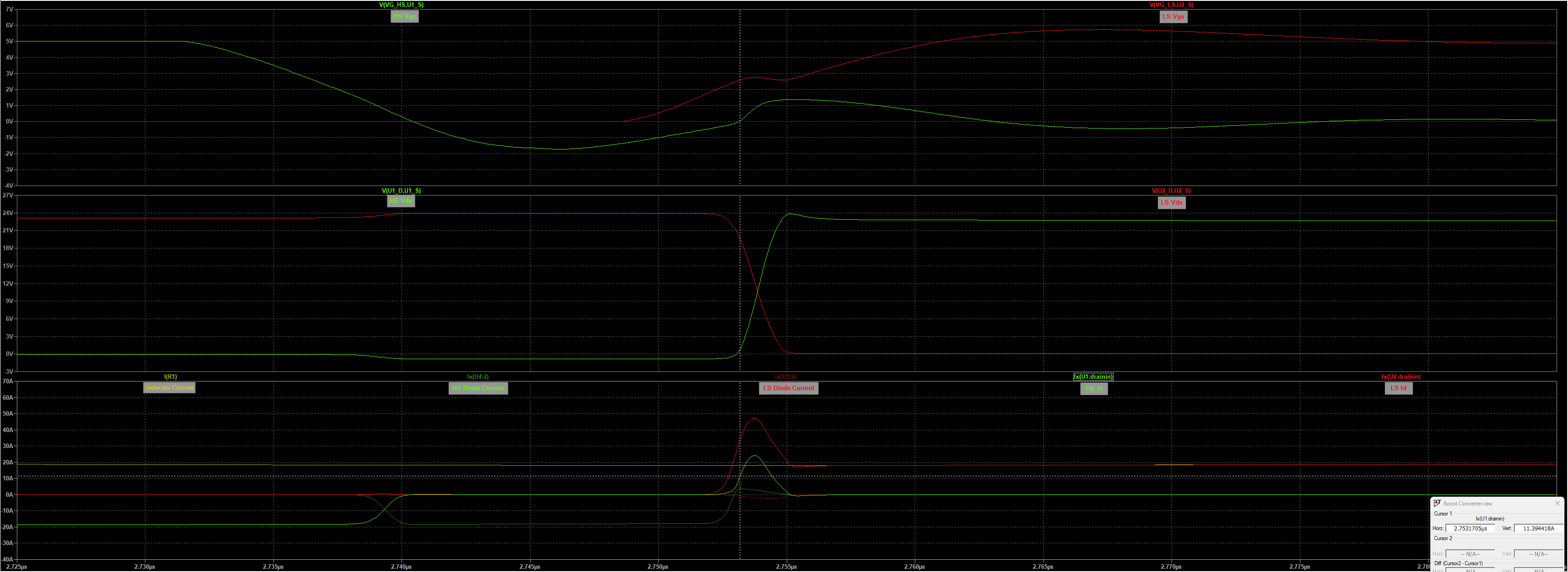
Looking closer it’s clear the FET is actually “sourcing” the current. With Vgs at 0V, there is 11A flowing. Granted, the scale of this is so small at <3ns, it probably doesn’t matter, but I’d just like to understand what the cause of this spike is, and if it’s an issue or not before I go spin PCBs.
Thanks for any feedback!