I am using 2 parallel EPC2302 on the half bridge inverter circuit to drive a 3-phase motor using NCP51820 gate driver. In some situations, the GaNs would burn when the boards are powered from a 48V battery in standby mode (power is ON).
What are things I need to check to find out what causes the GaNs to fail on this situation? Is it HW or FW issue?
There could be a few possible reasons.
Firmware: if the firmware is responsible for inserting dead time, make sure that is happening. A very long dead time can cause heating of the FETs… depends on your definition of standby (motor spinning but inverter not operating? Or motor not spinning?).
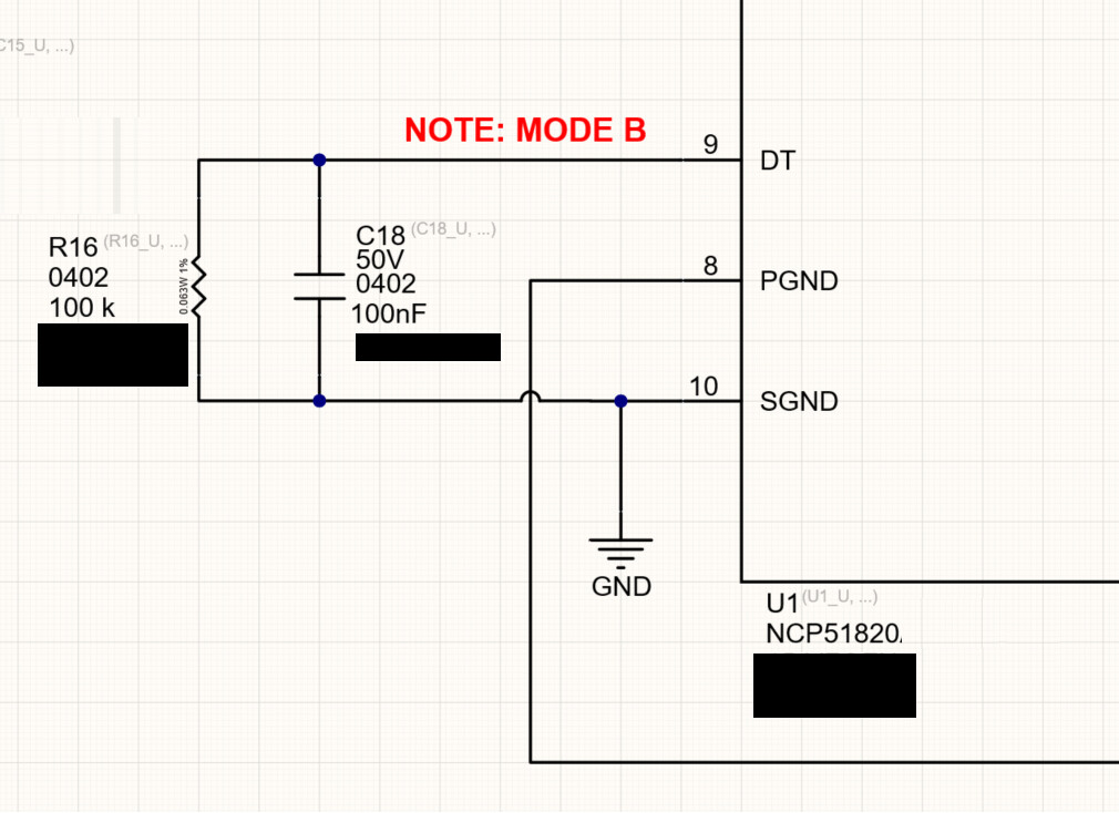
HW: The NCP51820 has a few modes for dead time. Beware, a few pins on it may be noise-sensitive and may need filtering (inputs, dead time setting pin, maybe others).
In standby mode, you could look at the gate drive signals, to be sure they are acting as they are supposed to. That should narrow down whether a firmware or HW issue.
If no signal is present, then dead time isn’t a concern. Continuous 48V is also not a concern (the FETs are rated to 100 V continuous… 48 V is less than half the rated voltage). Debugging ideas for you:
if standby mode, have the firmware set the gate driver’s Enable pin low (i.e., drive it low, not just open circuit). See the Enable (EN) section of the gate driver data sheet
check the output of the controller: is it a GPIO pin that is driven low, or rather set to input (high impedance)? If high impedance, perhaps in spite of internal gate driver pull-downs, it is floating up anyway. You can look at this, and determine if there is an issue, and what to do (set controller pins to drive low, or add pull-down R on gate driver inputs, etc.)
noise: check for any system noise (including floating/multiple grounds) that could cause the gate driver to turn on
check the gate driver outputs to FETs. There should only be a resistor, no diodes nor beads in the gate drive loop. No current sense resistor(s) in the gate drive loop
The gate driver EN has a pullup on the hardware so the gate driver’s output is always activated when there is power. The gate driver datasheet has built in protection for erroneous signals on the EN pin.
What are the risks of keeping the enable pin of the gate driver always ON?
Will a noise on the PWM inputs of the gate driver cause damage to the inverter?
In a standby state, disabling the gate driver may be a good idea. I’m not sure how your code works, a potential danger is the firmware changes the pins that drive the gate driver, and a glitch occurs. On the other hand, if the gate driver is disabled, then the gate driver can enter a low-power state (less drain on the batteries due to quiescent current), and it will not respond to any inputs until the firmware is ready to resume operation. The NCP51820 data sheet shows a bypass cap on EN pin, and the high and low input pins have filtering on EPC’s evaluation boards. I think there have been cases where these 3 logic input pins have needed filtering, ON Semi may be good to ask about details on these pins.
Or an extended on-time, or something else. You may want to look at it with an oscilloscope and other measurements, that may be more productive than discussing theories. This EPC GaN FET and this gate driver are widely used, and proven good, so something odd is going on. The shortcut to diagnosing it is likely measurements of a powered system.