DCDC buck converter short issue

Dear all,

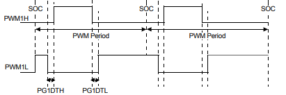
We are currently on a stage of firmware development for our own DC/DC converter based on dsPIC33CK256MP202. I’m using simple project code based on data sheet example “High-Resolution PWM with Fine Edge Placement” p.123, 5.3 Simple Complementary PWM Output mode. During FW testing on the device, I’m observing short on transistors on PWM1H part of the circuit, after that I can’t move forward of the development process.

Our project based on https://epc-co.com/epc/products/demo-boards/epc9143

Drivers: LM5113SD
Transistors: EPC2306 High side, EPC2302 low side.

Technical parameters: Voltage input: 36…58V Voltage output: 10.8…13.2V Rated power: 1000W Output current: 85A Quantity phases: 2 pcs Protection: UVLO, OVP, OCP, OTP Frequency: 500 kHz Type topology: Synchronous Buck DSP controller: dsPIC33CK Type transistors: GaN

Please help to find solution, Thank you.

Hello,
could you post some waveforms of the issue you are seeing? (PWM in signals, switch node, inductor current, etc). We have some recommendations on measuring high speed devices here: AN023 Accurately Measuring High Speed GaN Transistors.pdf (epc-co.com)
Did you also follow some of our recommendations for implementing GaN successfully? You can find additional material here: GaN Design Support Center for EPC Products | EPC (epc-co.com)

Hello,

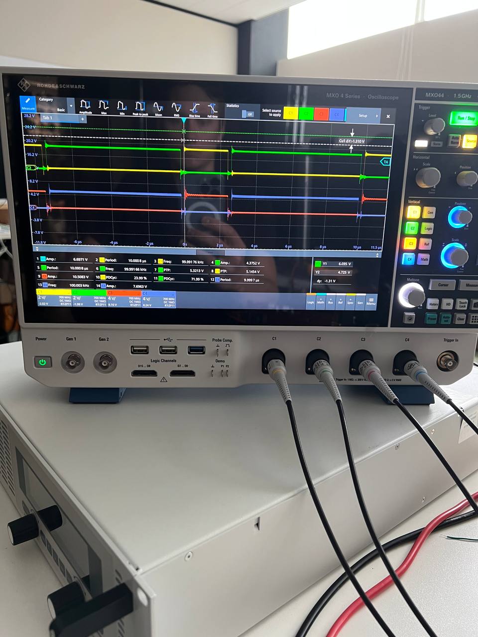
can you please check the pwm outputs of the microcontroller (PWM1H & PWM1L) to prove the dead time (PG1DTH & PG1DTL), without powering the output stage.

image

Hello Lilviu, Andrea,

Thank you for your response.

During debug process, I unsoldered transistors and after that I can safely observe waveform on oscilloscope, please find photo in attachment.

green/yellow input from dspic33 to driver, blue and red output from driver to transistors gates.

The signals are there, the dead time is visible.

Has the converter operate for a while before crash or it is hapend instantly on start up?
How did you determine the short circuit?