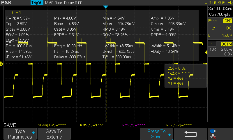
Hi, I have a question about my card, I did a pcb design using the EPC23101 and the EPC 2306 as an inverter for my inverter 3 phase for bldc motor, the problem when i test with 3 phase i dont get what i should get as you see in the image my Vin=12V
Hi, and thanks for writing in. I agree, the waveform doesn’t look good. Perhaps there may be a fairly simple way(s) to fix it.
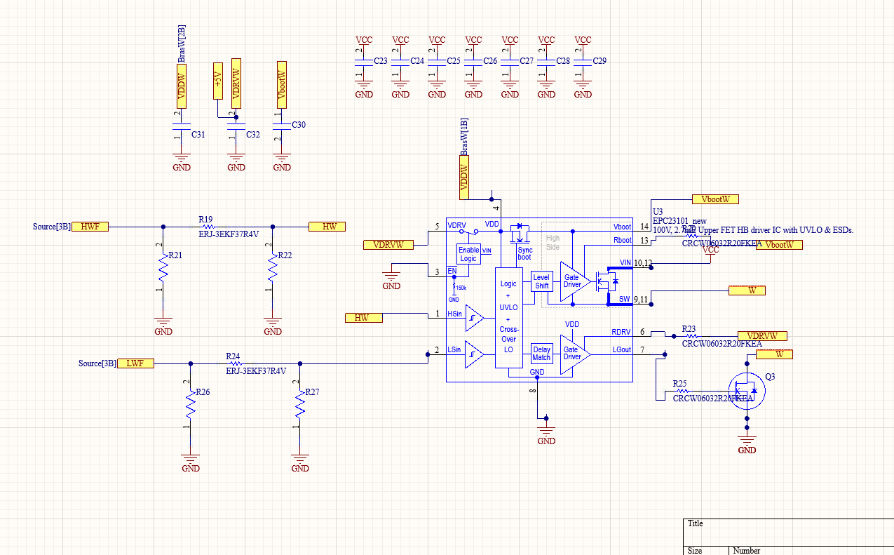
Is your frequency 10 kHz? On the pin VbootW there is a capacitor, it needs to be large enough to hold up the gate drive voltage for the on-time. The motor drive evaluation board that uses EPC23101, board part number EPC9173, uses 3.3 uF, but if 10 kHz, you’d need at least 4.7 uF.
Another factor is the dead time from your controller. GaN FETs can have very short dead times vs. silicon MOSFETs. Perhaps try 50 ns dead time.
Another thing to consider: due to your low input voltage, you may want to short EPC23101 pins 4 and 5, because the internal switch need Vin at least 10 V, and you may be getting close to that value.
Please note: EPC23101 is a very good part, but not production released, and there is no public schedule for production release. If this is an issue for your, then perhaps EPC23102 (similar, except 2 smaller FETs internal) has enough current for your project?
Hi
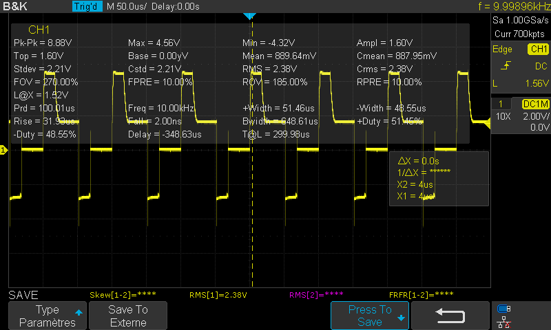
The problem was in my schematic the Cboot should be between Vboot and SW but in my case I do it between Vboot and GND
Now i get the good results
Thanks a lot