Hi,
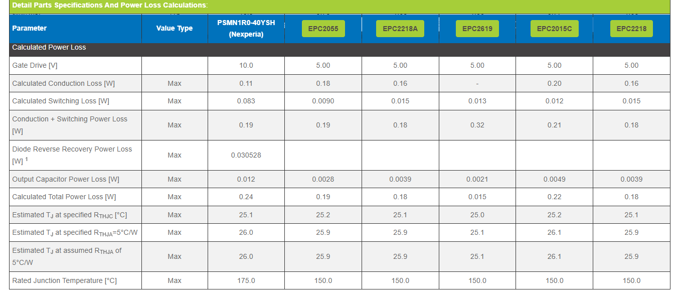
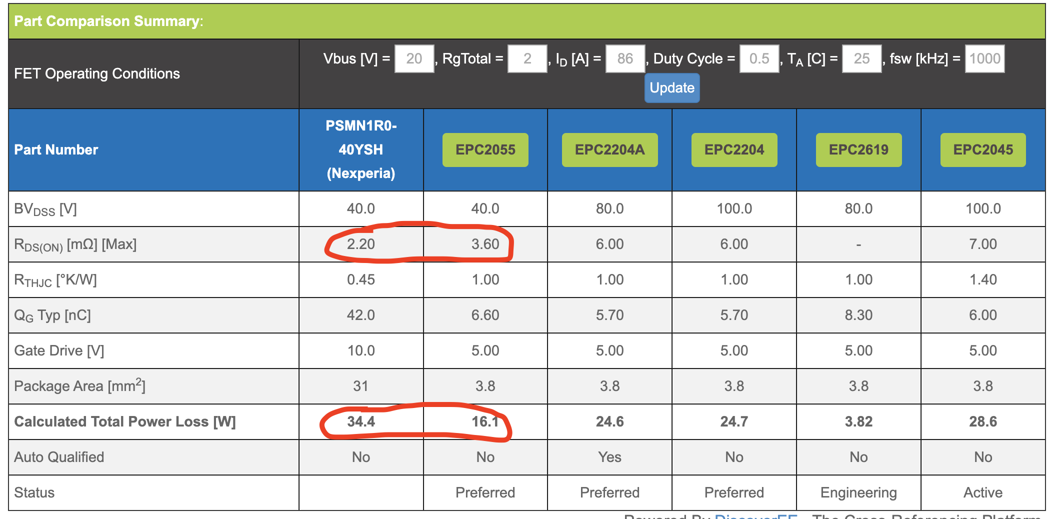
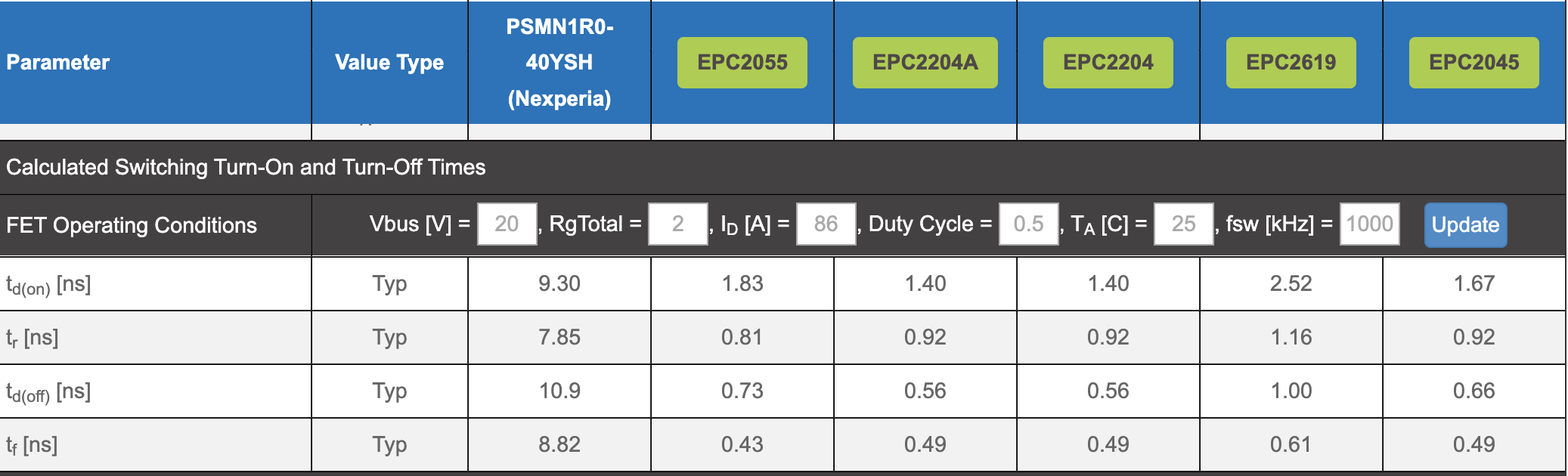
I am using the EPC Cross Reference Calculator and I’m comparing the PSMN1R0-40YSH. In the calculator, it shows that the PSMN1R0 will have greater power losses despite having a lower Rdson. I’ve narrowed this down to be caused by the calculated turn on and turn off times being different between the PSMN1R0 and the ganfets it’s being compared to. Why are these turn-on and turn-off times different between these fets in the calculator?
Hello,
this is because GaN FET have so much smaller charges for similar Rds(on).
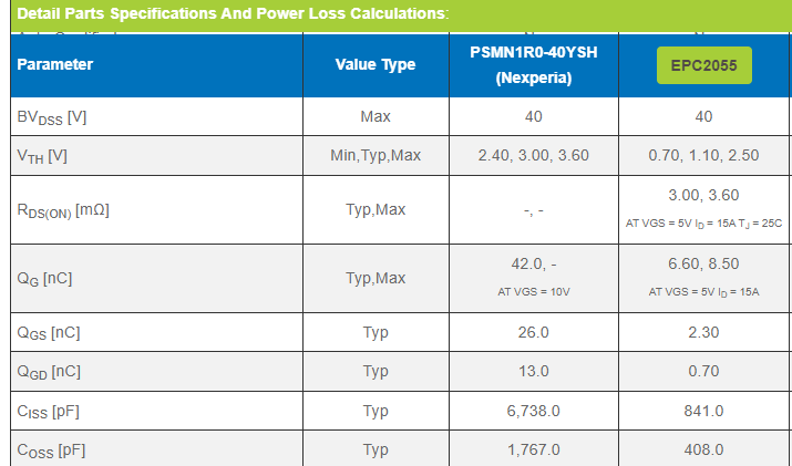
The overall comparison will of course depend on the switching frequency and how much switching losses contribute to overall losses (you can change that in the tool…)
Pardon me if I’m being ignorant, but wouldn’t rdson losses be the primary contributor to power losses for these high operating conditions (20V, 86A)? I don’t fully understand how the calculator is producing these numbers, are the switching losses of the psmn1r0 so high that the epc2055 is able to outperform it just from having lower switching losses?
When I set the duty cycle to 100 to remove the effect of switching losses, the EPC2055 is calculated to have less power losses, despite having higher rdson. Wondering what is going on here.
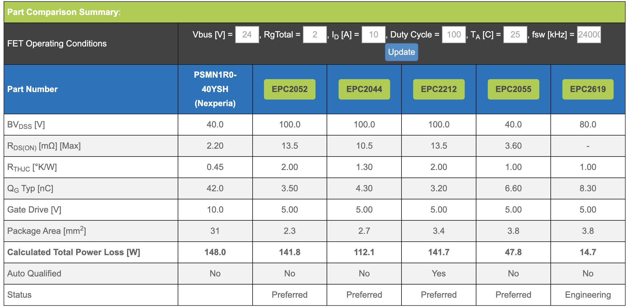
Unfortunately the tool only supports switching applications so even if you use duty cycle=1 (not 100) it will still add the switching losses to the total (the assumption is that you are actually 99.99% duty cycle)
If you are working at a lower switching frequency you can change that, and if you use a small enough number the switching losses will become smaller and smaller, and the cross will show more similar Rds(on) parts.
But if that is the case you might not be taking advantage of GaN performance…
Thanks, fixing the duty cycle makes the numbers make some more sense, but I have another question, when reviewing the math for the comparison between the fdmc8010 and the epc2066 it appears that the fdmc rdson is being calculated when driven at 4.5v, while the epc2066 is driven at 5v. The calculator seems to recognize that 10v is the correct gate drive voltage, as seen in the figure of merit math, but for the fdmc, but the rdson is calculated using 4.5v drive voltage. This doesn’t seem like an apples to apples comparison to me, especially when at first glance, it seems that the calculator recognizes that the fdmc should be driven at 10v. What’s going on here?