Hello,
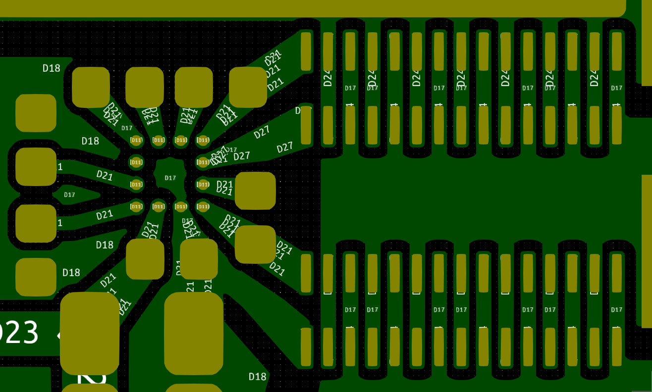
in one of my current projects, I’m using the EPC2066. Here is a picture of a half bridge with the associated gate driver:
I connected pin1 of the EPC2066 as gate and pin 2 as gate return. However, I did not connect the other source pins to pin 2. Is this permissible, or could it cause problems during operation? (Only the top layer is visible in the picture).
Best regards,
Jan Hermes
Hello Jan,
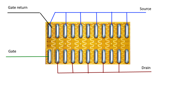
this is not recommended, as it will cause the device active area to not be fully utilized. The chip scale package of the EPC2066 has virtually no internal common source inductance, so the start point for Gate return can be done on the PCB itself as this diagram shows:
You should also take a look at the layout of the half-bridge board of the EPC 2066:
EPC90149: 40 V, 40 A Half-bridge Development Board (epc-co.com)
The gerbers are available at the link above, and more GaN resources are here:
GaN Design Support Center for EPC Products | EPC (epc-co.com)
Thanks for the reply,
what exactly do you mean when you say that the device active area is not been fully utilized?
I thought the source Pins of the EPC2066 are internally connected, so connecting the other souce pins to pin2 would only give the benefit of slightly decreased gate loop inductance in my case.
My Idea was to have the star connection inside the Epc2066 for best power gate loop isolation.
Sadly i already got the PCBs produced this way.
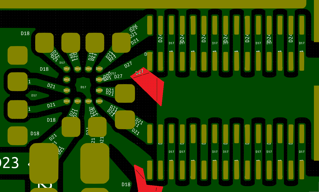
I could test it like it is and if i run into Problems with the switching behavior, I could add a copper bridge like this (marked red):
What dou you think?
I know the EPC90149 and already looked into it.
Hi Jan,
The source pins of EPC2066 are connected internally, but it isn’t as low of a resistance connection as an external (i.e. on the board) connection would be. The inside of the FET is made up of small FET sections going to the various Source pins. So, the Rds,on of the FET will be a bit higher than it would be if all the Source pins were connected on the board. Yes, you could indeed test your board as you have it, as long as you are aware that the efficiency may suffer a bit. Also, since that Source pin has extra resistance to the others, gate-source voltage may be a bit different, but probably not an issue for first tests.
Yes, the quick patch you show could be good to test if you see issues.
1 Like