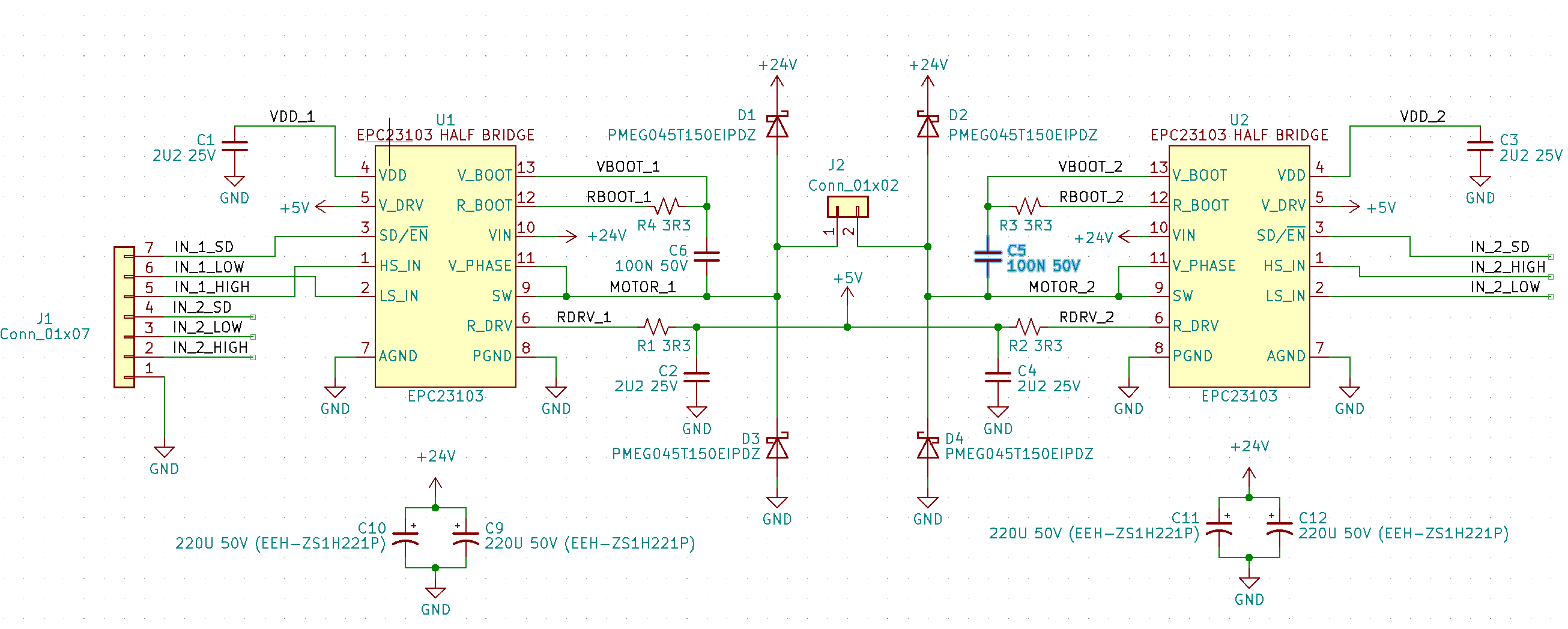
I’m currently trying to use a pair of EPC23103s on a test board to implement a full H bridge for a dc motor (voice coil). I’ve put together a prototype board (schematic below) but it’s not working as expected.
Each half bridge works independently. If I ground one lead from the motor, I can activate the high side of one bridge (HS_IN pulled to 3V3, LS_IN and /EN pulled to 0) and get full voltage (24V) and current across the coil. (Conversely with the low side.) However, when I activate HS_IN of one bridge and LS_IN of the other, I get 2V at both bridges’ outputs.
I’ve tried simultaneously pulsing both HS_IN_1 and LS_IN_2 at 1kHz, 5kHz, 10kHz and 50khz, at both 10% and 50% duty cycles. I’ve also tried holding HS_IN_1 high while pulsing only LS_IN_2, and pulsing HS_IN_1 at 90% duty cycle with LS_IN_2 at 50%. None of these tests made a difference – the pk-pk voltage output of each bridge never exceeded 2V. Additionally, the outputs of both bridges are going to 2V simultaneously with the pulsing, so the actual current across the coil is effectively zero.
Later, I drove the motor with an externally applied force, driving approximately 10V across the coil, at which point one of the bridges spontaneously combusted. I was quite surprised by this as I’m using some pretty beefy clamp diodes and I didn’t see the voltage from the coil ever exceed the 0V-24V range.
This schematic is (supposed to be) two direct copies of the circuit used on the EPC90151 evaluation board, without the input logic buffering, and with flyback diodes on the outputs. It’s not clear to me why each bridge would work independently but fail when driven together.
Hello,
I’m sorry to hear about your troubles.
For the first topic, I want to make sure you have seen the spec in the datasheet regarding the min and max pulse widths for the control signals (30ns and 200µs). More details are provided on the page 10 section called “gate driver”, but basically the LIN and HIN need to be continuously switching for the internal circuits to operate correctly. It would seem like some of your test conditions would not meet this criteria. However, some should (50kHz test). Do you have some waveforms for this particular condition?
For the failure, were the external diodes still OK? How were the IC inputs modulated during this test?
I think it is probably better to have a more detailed discussion via email. Could you please contact our East Coast FAE Brian at brian.miller@epc-co.com?
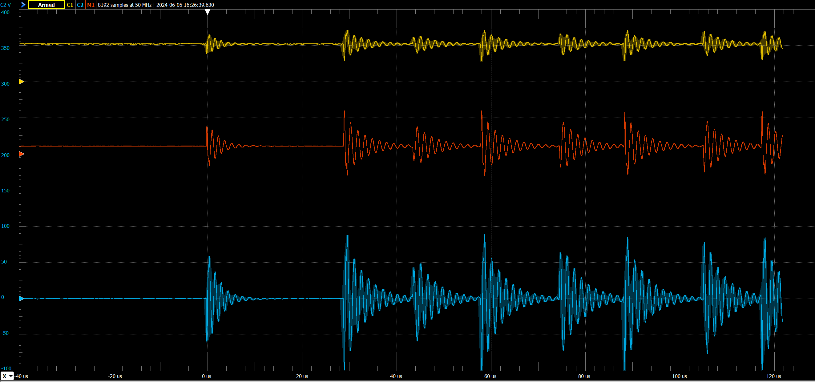
(Yellow and blue are EPC23103 outputs; the red signal is the differential signal across the motor coil. Yellow 23103 is being driven on LS_EN; blue driven on HS_EN.)
Different result with no change in experimental setup, but still very peculiar. The yellow signal is behaving as expected now (a 50% PWM) but only for about 1ms. The blue signal is slowly increasing to about 2V over about 1500 us, then jumping to 24V almost instantaneously. After about 2ms, both bridges stop responding.
Thermals indicate the yellow IC is warming slightly but the blue IC is not.
Regarding the first board’s immolation: only the EPC23103 failed. The clamp diodes remained intact. IC inputs are 3V3 50% duty cycle PWM, with a bit of jitter since I’m just bit banging the PWM off an Arduino for these preliminary tests.
I’ve also reached out to Brian via email and linked him here. Thanks for the suggestion, and thanks for your reply! Hoping we can get to the bottom of this.