I’ve been reading white paper WP008, on the subsection “Effect of common source inductance”, it is recommended to add a ferrite bead at the gate drive turn off path.
Are there some ferrite beads EPC recommends using for this application? They are inductive elements in the lower frequencies, and I’m cautious that using them might cause oscillation on their own, during device turn-off.
Hi Greg,
we have not really used this method in our reference designs: it could work but is untested from our side. In general I agree with your comments about possible side effects, so caution should be used with this method.
I would recommend you take a look at our many half-bridge boards and reference designs.
With a good layout ( How2AppNote007 - Design an eGaN FET Based Power Stage with an Optimal Layout.pdf (epc-co.com)) we have not had any issues with common source inductance.
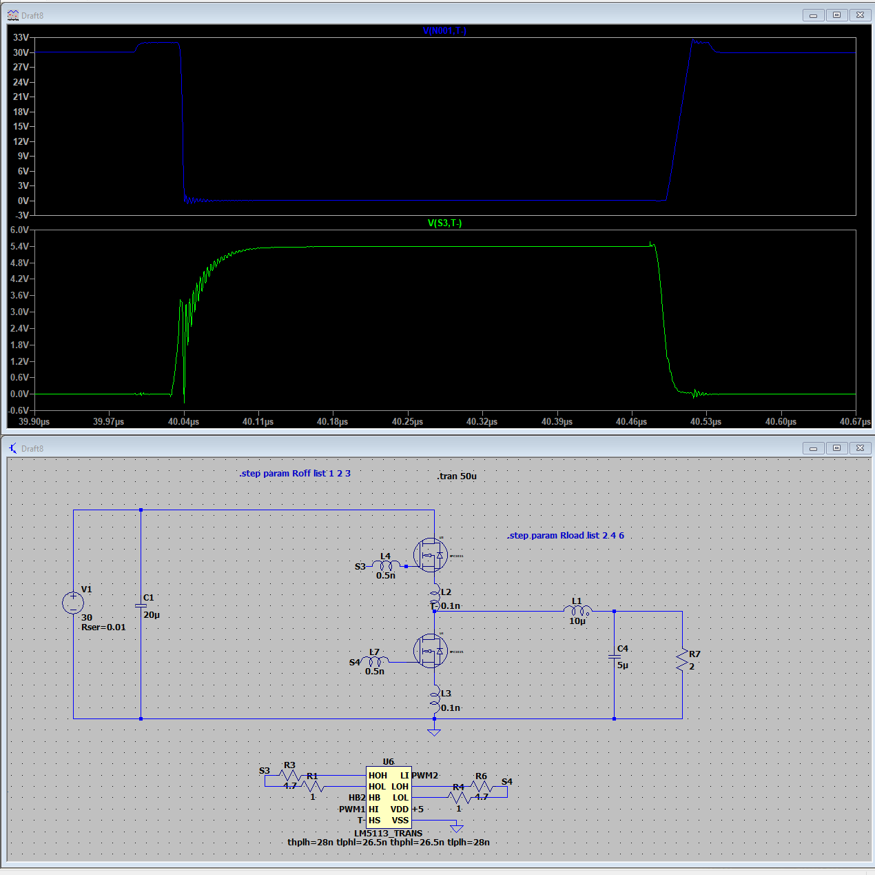
I’m playing with a half bridge module I’ve made, following EPC recommendations (optimized power loop layout, gate drive used is lm5113 with the smaller BGA package ie tiny gate loops etc), but having it hard switching, no matter the gate resistor, there is oscillatory behavior on the upper device during turn on. I’ve simulated this on LTSpice and it seems agreeable with the bench behavior. I suppose this is normal behavior is unavoidable when hard switching?
Please have a look below at the photos of simulation / oscilloscope reading.
(Top graph being Vds on the device, bottom the gate-source, approx 6A output current on this simulation)
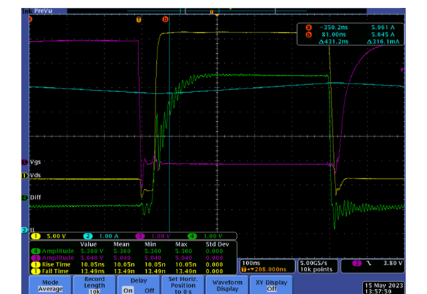
And on the bench with the similar parameters (Ron is a bit higher):
Yellow trace being the midpoint voltage, purple the lower Vgs (1GHz passive probe), and green the top Vgs(100MHz differential probe).
My thoughts so far is this seems unavoidable, and perhaps in a hard switching scenario I should try and dimension the turn-on resistance based on the maximum load current, as to not cross the ~1V threshold?
Hi Greg,
which device are you using?
You could also take a look, and maybe test, the half bridge board for the device you are testing to give you a better idea of what is possible.
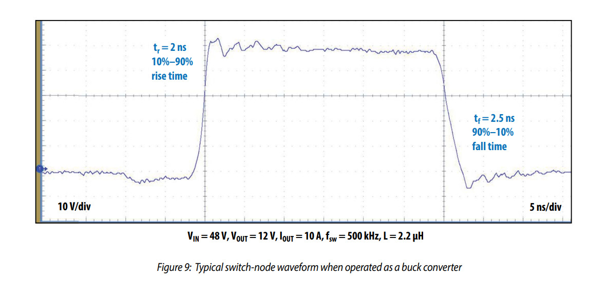
For example, this is the measured waveform from the EPC9097 which is the half-bridge board for the EPC2204: