Dear Experts,
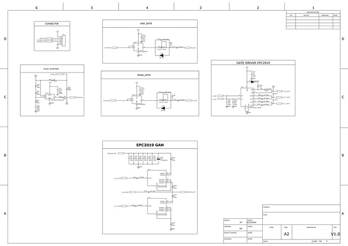
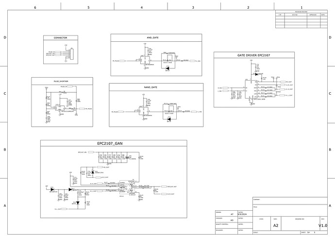
I am working on two GaN-based schematics (attached) and need your help. I refer Evaluation Board Schematic for the Design Schematic. For schematic design for Epc2019, I refer to Schematic EPC9014. and for design, Schematic of EPC2107 I refer to the schematic of EPC9063 My application requires generating pulses with these specifications:
Pulse Widths: 40ns, 100ns, 200ns, 2µs, 5µs, 10µs, 20µs, 50µs
Voltages: 40V, 80V, 100V, 120V, 140V, 160V, 180V, 200V
Observations:
With EPC2019, when I increase the drain voltage above 20V, my power supply goes into constant current (CC) mode even though the driver signals remain unchanged. Also, the gate voltage on the high-side GaN increases with the drain voltage.
With EPC2107, the gate voltage on the high-side GaN increases with the drain voltage. For example, with a 5V gate signal and 30V drain voltage, the gate voltage measures ~32-33V, and the output pulse is only ~25-26V.
Please review these schematics, and let me know the potential causes for these issues and any suggestions for improvements.
Best regards,
Atul

