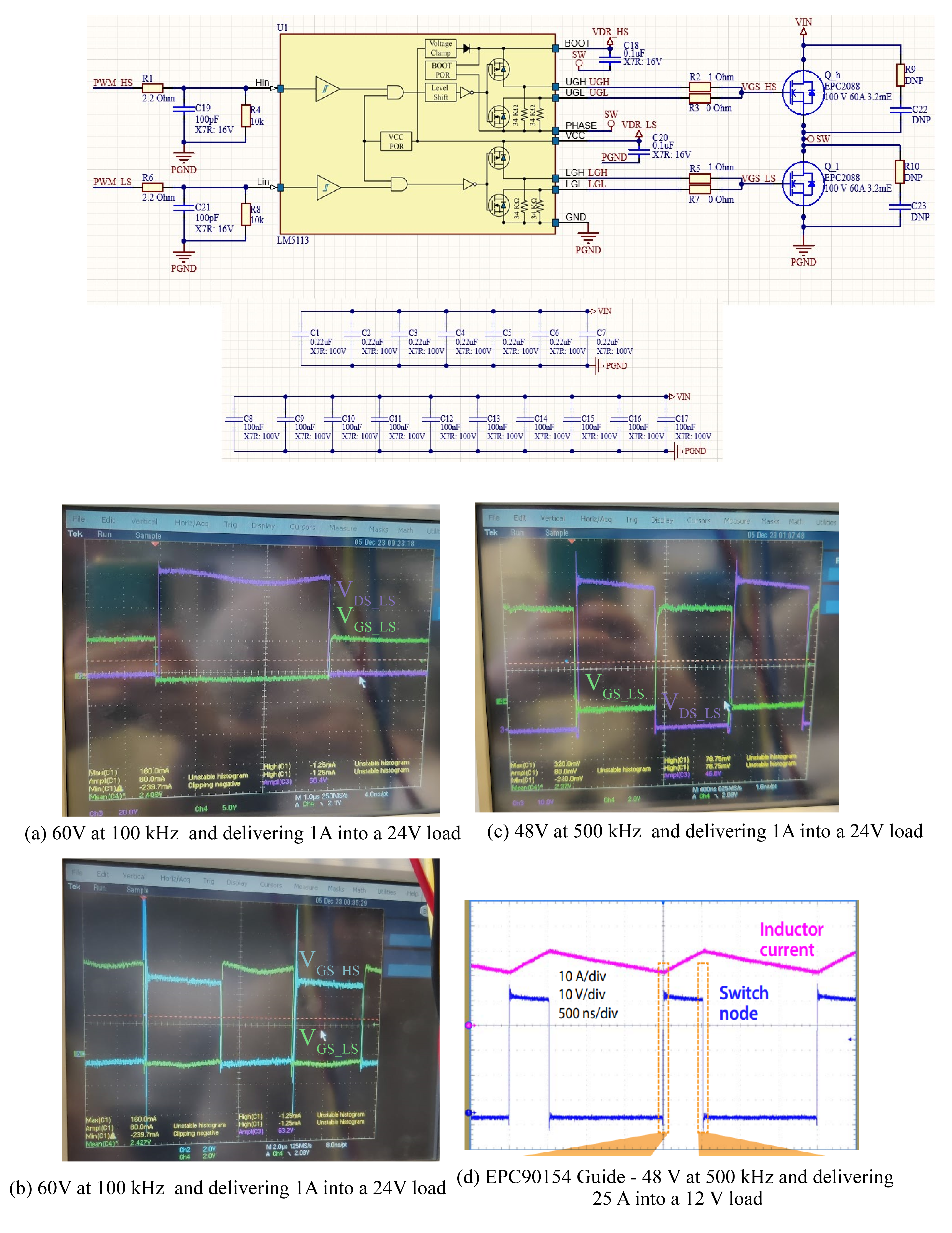
I have created my own version of the EPC90154 following your layout guidelines but with isolated driver voltage supplies instead of bootstrap (No ripple with 100uH inductor and deadtime = 30ns). However when testing it, I am finding some issues. I attach a figure with the schematic and osciloscope captures for easier explanation.
1º) An oscillation on the switching node voltage.
This effect is more clear at lower frequencies (100kHz) but also exhibited with a slope behaviour on greater frequencies (500kHz). I have noticed that your Quick Start Guide also exhibits this behaviour at 500kHz but does not show anything for 100kHz. Is it something common? Maybe related to the resonance frequency between the capacitance of our voltage supply and the inductance of the cables?
2º) Not equal 5V in the gate drivers voltages and even negative voltage.
Could this be related to the internal bootstrap of the driver that we are not using?. The supply is given by an indiviudal DC/DC followed by an LDO of 5V for each high and low side.
Hello Miguel,
thank you for using our devices.
You used LM5113, which is a pretty outdated driver. In its app notes and datasheet TI states to use an external bootstrap, and Zener clamping. This is because the internal bootstrap is weak.
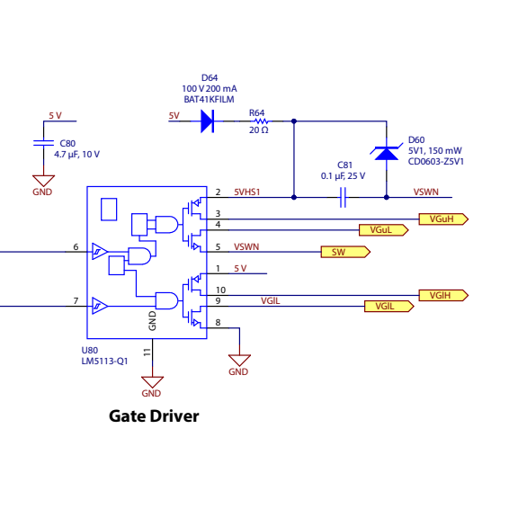
Please have a look to our EPC9163 for an example. See below schematic extract.
The high side gate drive is not that bad in your case, and you have to expect 0.5V or so lower drive because of bootstrapped supply.
Regarding the switching node oscillation, is it following the input (bus) voltage behavior? It might then be solved by some added bypass capacitance. The cause might be cabling inductance from PSU resonating with the bypass caps.
It was my bad that the schematic had the wrong part number, the actual driver is the LMG1205 which can be easily replace with the UP1966E (didnt include firstlly this driver for its lack of documentation).
Sorry, I do not undersant what you mean with the bootstrapped supply. I am using isolated power supplies so the internal bootstrap should not be working at all and therefore I don’t have an explanation for voltage differences.
Yes, indeed the high side looks better but I see both incorrect:
HS: Goes from -0.5V to 5V
LS: Goes from -0.5V to 6V
When both are supplied with fixed 5V. Any ideas for this reason?
Regarding the oscillation, yes its most likely that the cables oscillate with the input capacitance, I will check it in the lab this week. However, it is noteworthy that this same issue happens to you too in Fig. d (taken from EPC90154 user guide) with a little slope. Did you also face this same oscillation?.
Hello Miguel,
sorry now I see you are using isolated DC/DC followed by LDO to regulate gate drive to 5V.
In general, the negative gate drive voltage of about -0.5V does not make sense. I have no explanation for that except an artifact or error in measurement… the return of the gate driver is connected to the source of the FETs, so it should be zero. Where is the scope probe connected?
Regarding the on voltage, you see 5V (which is good) and 6V. 6V should be actually 5V. One possibility is that LDOs can get out of regulation if they are subject to capacitive coupling to high dV/dt edges, that can pump some current in the feedback node. Can you share the gate driver supply schematic? Again, measurement artifact needs to be ruled out.
You were correct, it was a measurement issue, the probes were not properly calibrated, thanks. Regarding the oscillation, I have verified with simulation that yes this is an oscillation issue between the power loop capacitors and the supply cables. Something easy to solve by placing a large capacitor in the input. However, noteworthy to mention that this is going to happen to most of the people that uses the evaluation board you provide (EPC90154) due to the low capacitance values. Could be good that you mentioned this risk as also applies to your user guide results as seen in Fig (d).
All in all thank you very much for you time and valuable help!.