I design the current source with EPC2023.
The worst case of FET condition below:
I_max = 60A, Vgs = 2.577V, Rds_on = 14.6mOhm (52.6W)
This condition will be within 1ms
How to know or calculate the temperature rising in this period?
Thank you
I design the current source with EPC2023.
The worst case of FET condition below:
I_max = 60A, Vgs = 2.577V, Rds_on = 14.6mOhm (52.6W)
This condition will be within 1ms
How to know or calculate the temperature rising in this period?
Thank you
Hello,
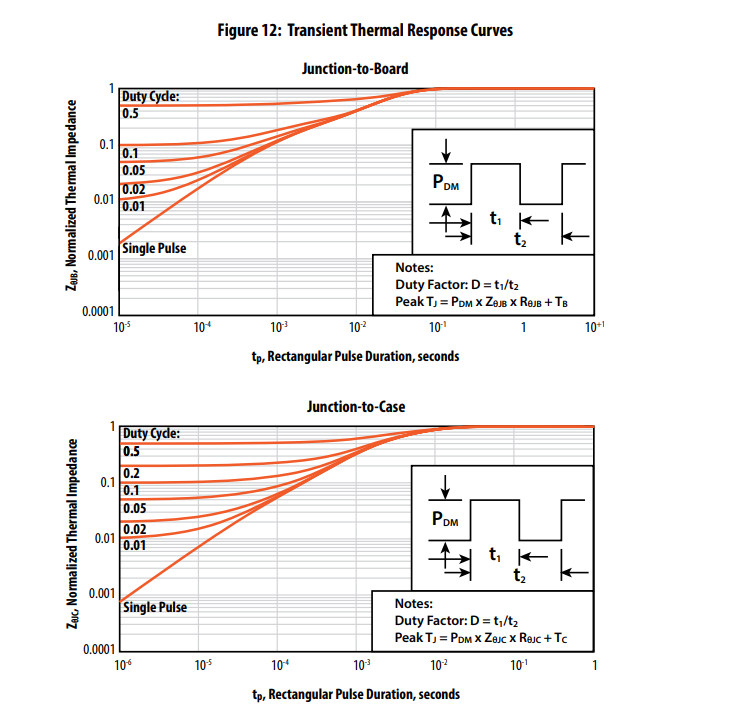
to calculate the temperature rise you have 2 options:
In both cases, please note that these models stop at the device boundary (either the top or bottom of the device); and depending on your assembly and thermal system you should take into account the rest of thethermal system in your calculations.
Hi Andreagorgerino,
So in my case, I will calculate the junction to board as below:
P_DM = 52.6W
Z_JB = 0.1 (single pulse at 1ms)
R_JB = 1.1 (C/W per datasheet)
T_B = 25 (oC as assumption)
=> Peak Tj = 52.60.11.1+25 = 30.7 oC.
Could you help to check my calculation?
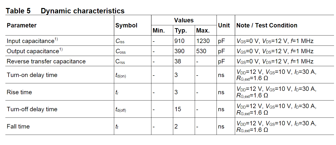
Another question, I cannot find the rising/falling time in the datasheet, where I can get these parameters?
Thanks.
Yes, the calculation for the peak temperature is correct.
For rise and fall times we do not specify them in the datasheet as they depend on the circuit they are measured on.
Our recommendation is to use our LTSpice models ( EPC Device Models (epc-co.com)) and setup a simulation with the gate driver (at least its output stage) to get an estimate of these values.