If I look at the SOA curves on page 5 of the EPC2012C datasheet, I see that an 8A pulse with Vds=3V can last for a 100mS.
Am I right to assume that this situation only exists when the load is a large capacitor? In a regular buck application, where the switch node load is an inductor, the Vds will be controlled by the RdsON (100mOhm will give 0.8V)?
Secondly, do the SOA curves just reflect the max temperature of the die, taking the transient thermal resistances into account? In my buck converter, I need to be able to deliver slewing current of +/-8A for repeated pulses of 200uS. How can I use the SOA curves to find if a half-bridge made of EPC2012Cs can do this?
Hello, thank you for your question. I make the discrete datasheet SOA curves. Just as you suggested, the methodology is to use a thermal model, assuming Rthjc conditions, and calculate the maximum power dissipated in the FET such that the die temperature does not exceed 150 deg C (max).
The SOA curves in the datasheet are useful when power dissipation is constant, and lines are shown for rectangular pulse durations of 100 us, 1 ms, etc.
You are right that if the FET is operated in the linear regime at a current of 8A, that the power dissipated is given by I^2*Rds(on). Reading off the dashed black Rds(on) line from the EPC2012C SOA curve shows that 8 A corresponds to Vds of less than 2 V, and is far below the thermal limit, even for relatively long pulses of many ms.
For a specific application requiring a more complicated thermal analysis (e.g., modeling time-dependent Vds and load current), one could use the part-specific thermal model provided here: EPC2012C Thermal Model.
Hello,
yes, the SOA curve is drawn with the assuption: Tj= max rated. The curves are drawn by using the transient thermal impedance curves and calculating how much power can be dissipated to reach that Tj (starting at 25°C)
the power limited curves (diagonal ones) mean the device is seeing both voltage and current: this will not happen in normal operation of a buck converter, except during switching events in which case the times are much much shorter than the curves shown here.
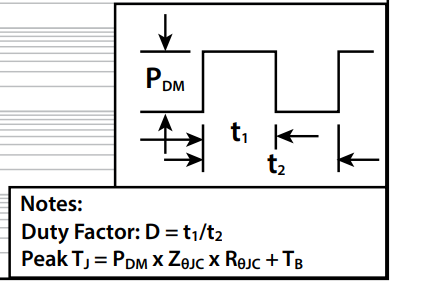
For your example you cannot use the SOA curve. You can use this calculator GaN FET Thermal Calculator (epc-co.com) to estimate losses during your 200µs pulse, and the use the transient thermal impedance curves to calculate the deltaT during each pulse (or for the train of pulses), with this formula: